Evaluating Bolt Joint Integrity in ANSYS Mechanical
Written By: Paul K. Lee (Ph.D, P.Eng) and Martin Vézina (Eng, MASc)
The content in this article is for general knowledge and does not recommend any particular approach for any given application. Engineers must always critically evaluate their models and results for their application.
When joining two plates with bolts, the primary engineering goal is to ensure that the assembly acts as a single structural unit under load. In ANSYS Mechanical, evaluating whether a bolt is “working” goes beyond checking if it breaks; it requires a deep dive into the contact mechanics between the plates and the load distribution within the fastener.
For ANSYS users, mastering the Contact Tool and understanding the difference of Elastic Slip versus Sliding Distance is essential for validating joint integrity.
1. Contact Tool
The Contact Tool is a useful tool for verifying a bolted connection. In a preloaded bolt scenario, we typically define a “Frictional” contact between the two plates.
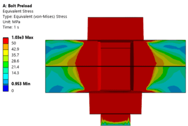
• Pressure & Penetration: The Contact Tool allows you to visualize the contact pressure distribution. For a well-jointed pair of plates, you should see a “pressure cone” extending from the bolt head/nut toward the interface. If the pressure drops to zero in areas where it should be clamped, the joint may be losing contact.
• Status Evaluation: It provides a clear view of whether the interface is Sticking, Sliding, or Near (opening). A successful bolt joint typically maintains a significant “Sticking” region around the bolt hole to transfer shear loads via friction.
2. Elastic Slip vs. Sliding Distance
Distinguishing between Elastic Slip and Sliding Distance is critical for determining if your bolt is functioning as intended or if the joint has failed.
• Elastic Slip (The “Micro” Movement)
In ANSYS, even when a contact status is “Sticking,” a tiny amount of numerical movement occurs—this is Elastic Slip. It represents the reversible deformation of the surface roughness before true sliding occurs. If the elastic slip is within the allowable tolerance of contact formulation (Frictional), the joint is technically still “Sticking.” It indicates the joint is stable and the friction is successfully resisting the applied lateral loads.
• Sliding Distance (The “Macro” Movement)
Once the shear force exceeds the frictional capacity (F = μ·Fpreload), the status changes to “Sliding,” and ANSYS records Sliding Distance. This is the actual relative displacement between the two plates. Large sliding distances indicate that the bolt is no longer holding the plates via friction alone. At this point, the load shifts from “Friction Grip” to “Bearing,” where the bolt shank physically contacts the side of the hole. This is often a failure criterion in high-precision or fatigue sensitive structures.
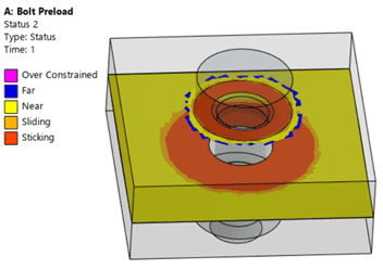
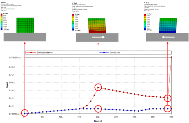
Here is an example of shear deformation during elastic slip and frictional sliding:
3. Practical Application: Is the Bolt “Working”?
To evaluate whether the applied bolt is functioning properly, verify the following three-step validation:
1. Preload Verification: Use the Bolt Tool to check the “Adjustment” and “Working Load.” Ensure the bolt has reached its target preload before the external load is applied. The maximum working load in the bolt should be less than the permissible bolt load (proof strength or allowable load) specified for the bolt.
2. Contact Status Mapping: Use the Contact Tool to ensure the “Sticking” area is sufficient. If the entire interface is “Sliding,” the bolt preload is likely insufficient for the applied load.
3. Stress Concentration: Check for stress concentrations at the bolt-hole interface. If the plates are sliding, look for “Bearing Stress” on the hole walls, which can lead to local yielding.
4. Conclusion
In reality, a bolted joint does not fail only when the bolt fractures, but also when the plates move unexpectedly. By monitoring the sliding distance and maintaining a stable contact pressure profile, engineers can predict the onset of joint slip long before physical testing begins.
For ANSYS users, these tools transform a simple “pass/fail” check into a comprehensive assessment of joint integrity, ensuring that the bolted joint remains rigid, reliable, and safe under its maximum design load.
For more information and deeper discussions, contact our Engineering Training team.